


How to Choose an XRF plating Thickness Analyzer?
18-08-2026
An XRF plating thickness analyzer measures the thickness of individual layers in a multilayer plating stack — such as nickel, copper, tin or gold platings — without cutting, cross-sectioning, or otherwise damaging the part. It is widely used for verifying plating quality on components ranging from magnets to electrical connectors, where layer thickness directly affects corrosion resistance, conductivity, and product lifespan. For multilayer platings, however, the plating structure, sample geometry, measurement area, and analysis algorithm can all affect measurement performance.
Application 1: NdFeB Magnet Plating (Ni/Cu/Ni)
NdFeB (neodymium-iron-boron) magnets offer strong magnetic performance and are used widely across electronics, electric machinery, medical devices, toys, hardware, and aerospace. Because the base magnet material is prone to corrosion, it's typically protected with a three-layer plating: nickel, then copper, then a second nickel layer (Ni/Cu/Ni).
This structure presents a particular measurement challenge because the same element — nickel — appears in two separate layers. The ability to analyze repeated elements in multilayer platings therefore depends strongly on the calculation method used by the analyzer.
FP (Fundamental Parameters) is a common XRF calculation method and generally requires reference standards for calculation. Conventional FP analysis has limitations when analyzing repeated plating layers and non-metallic or light-metal platings.
EFP is an industry-used calculation approach that incorporates multiple factors, including primary and secondary fluorescence, target fluorescence, absorption/enhancement effects, and scattering background, through iterative calculation. It can require only a small number of reference standards for instrument-factor correction and can support analysis of repeated platings, non-metallic and light-metal platings, multilayer/multi-element structures, and organic layers.
INSIZE XRF plating thickness analyzers use EFP-based analysis to support multilayer plating measurement, including structures in which the same element appears in different layers, such as Ni/Cu/Ni.
Application 2: Connector Plating
Electrical connectors typically use contacts made from materials such as brass or phosphor bronze. Depending on the application, the contact surface may be plated with nickel, silver, tin, gold, or combinations of different plating materials.
Connector plating often involves small measurement areas and relatively thin platings. For example, gold-plated contact points may be much smaller than a typical flat test sample. In these applications, accurate positioning and repeatable measurement become particularly important.
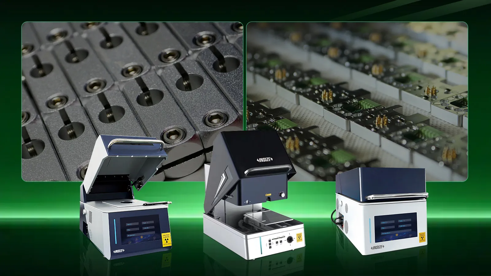
Choosing the Right Instrument
| Model | Tier | Design | Height range for irregular parts | Sample stage |
| XRF-PT230 | Basic | Down-facing | 0–30mm | Manual |
| XRF-FA350 | Basic | Up-facing | 0–70mm | Programmable, automatic |
| XRF-VF300 | Advanced | Up-facing, vacuum chamber | 0–30mm | — |
Down-facing vs. up-facing — A down-facing design (XRF-PT230) rests the sample on a stage below the detector, which suits flatter parts that sit stably on their own. An up-facing design (XRF-FA350, XRF-VF300) positions the detector below the sample, which can be easier to work with for irregular or bulkier parts, and pairs with a larger height range for handling greater variation in part geometry.
Manual vs. automatic stage — The XRF-PT230 uses a manual sample stage, suited to lower-volume or varied testing. The XRF-FA350's programmable automatic stage suits higher-throughput testing where consistent, repeatable positioning across many samples matters.
When to choose the vacuum model — The XRF-VF300 adds a vacuum chamber, which can improve measurement of lighter elements that are more affected by air absorption. It also extends beyond plating thickness to measure electrophoretic (e-coat) platings and RoHS restricted substances, making it suitable for buyers who need plating thickness and RoHS screening in a single instrument.
Frequently Asked Questions
Q: Can XRF measure the individual nickel layers in a Ni/Cu/Ni plating on NdFeB magnets?
A: Yes, with an appropriate multilayer analysis method. Conventional FP analysis has limitations when the same element appears in different plating layers. EFP analysis can support more complex multilayer structures, including repeated elements, while requiring fewer reference standards for instrument-factor correction. INSIZE XRF plating thickness analyzers use EFP-based analysis to support measurement of structures such as Ni/Cu/Ni.
Q: What's the difference between a down-facing and up-facing XRF plating thickness analyzer?
A: A down-facing analyzer places the sample on a stage above the X-ray source and detector, suited to flatter samples. An up-facing analyzer positions the sample above the detector, which is often easier for irregular or bulkier parts and typically supports a wider range of part heights.
Q: Why would I need a vacuum XRF plating analyzer instead of a basic model?
A: A vacuum chamber can improve the measurement of lighter elements that are more affected by air absorption. The XRF-VF300 also supports e-coat thickness measurement and RoHS screening in addition to standard plating thickness testing.
Q: Is XRF suitable for measuring plating thickness on small connector contact areas?
A: Yes. XRF plating thickness analyzers with suitable focal distance and positioning can be used for localized plated regions such as connector pins and gold-plated contact points, depending on the measurement area, workpiece geometry, plating structure, and required measurement performance.