


How to Use a 3D Scanner: Preparation, Scanning and Inspection Workflow
10-09-2026
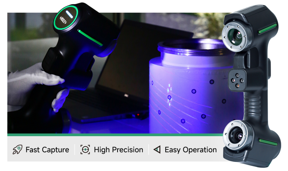
3D scanning is widely used for dimensional inspection, surface comparison, and reverse engineering. A scanner can capture the surface of a part without contact, but reliable measurement depends on more than the scanner itself. Workpiece preparation, calibration, scanning parameters, positioning, and point-cloud processing all affect the final result.
This guide explains the main steps of a 3D scanning process, from preparing the workpiece to inspecting the final 3D data. It also introduces automated scanning for repeated inspection tasks.
What Are the Main Steps in 3D Scanning?
A typical industrial 3D scanning process includes:
Prepare → Warm Up → Calibrate → Set Parameters → Scan → Process Point Cloud → Align/Mesh → Inspect or Reverse Engineer
1. Prepare the Scanner and Workpiece
Before scanning:
• Connect the scanner to the computer and prepare the scanning software.
• Clean the workpiece and remove dirt or oil.
• Apply positioning marks when required. A spacing of about 100 mm is recommended.
• Keep at least four marks visible within the camera view.
• Allow the scanner to warm up for about 15 minutes before calibration.
2. Calibrate Before Scanning
After warm-up, calibrate the scanner using the supplied calibration plate.
Recalibration is recommended when the operating temperature changes significantly. For the INSIZE scanning workflow, recalibration is recommended when the temperature changes by more than ±5°C.
Proper calibration helps maintain consistent measurement conditions throughout the scanning process.
3. Select the Right Scanning Mode
The scanning mode should match the geometry and detail of the workpiece.
| Scanning Mode | Typical Use |
| High-speed | Large surface areas |
| Precision | Small or detailed features |
| Deep-hole | Internal or deep recessed areas |
For complex parts, different modes can be combined. High-speed scanning can be used for the overall surface, followed by precision or deep-hole scanning for areas that require more detail.
4. Set Scanning Parameters
Before scanning, adjust the resolution and shutter settings according to the workpiece surface.
Surface reflectivity can affect the captured point cloud. For difficult surfaces, appropriate scanning parameters can help improve data completeness and stability.
The objective is not simply to collect more points, but to obtain usable data for the intended inspection or reverse-engineering task.
5. Scan the Workpiece
Start scanning after calibration and parameter adjustment.
Move the scanner steadily across the workpiece while maintaining sufficient overlap between adjacent scanning areas. Positioning marks help the system track the scanner and combine successive scans.
For complex parts, switch between scanning modes when necessary. Use high-speed scanning for larger areas and precision or deep-hole scanning for smaller or recessed features.
For repeated inspection of the same type of workpiece, however, manual scanning may not ensure consistent measurement results from one inspection to another, as results can vary between operators. In such cases, automated scanning can be considered.
6. When Should 3D Scanning Be Automated?
Automation is useful when the same scanning and inspection procedure needs to be repeated for multiple workpieces. Automation helps reduce human error and improve measurement consistency.
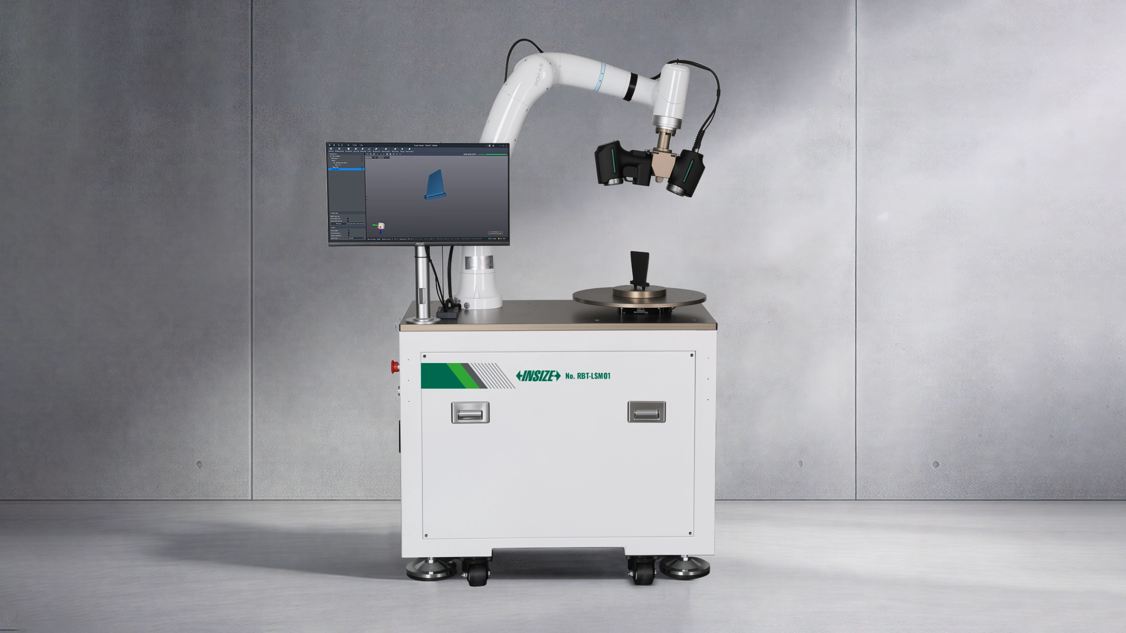
The INSIZE RBT-LSM01 Automated Scanner Measuring System combines a 6-axis collaborative robot, 3D scanner, high-precision rotary table, and automated measurement software. It supports automatic calibration, automated scanning, data transfer, and inspection report generation.
A typical automated process is:
Load the workpiece → Start the system → Automatic calibration → Automated scanning → Data processing → Inspection report
The operator places the workpiece on the scanning fixture and starts the system. The robotic arm moves the scanner while the electric rotary table rotates the workpiece in coordination with the scanning process. The scanned data is then imported into the measurement software for processing and report generation.
This setup is particularly suitable for repeated or batch inspection, where consistent scanning and reduced manual operation are important.
7. Process and Align the Point Cloud
Scanning is only the first part of the measurement process. The captured point cloud normally needs to be processed before it can be used for inspection.
Typical steps include:
1. Remove unwanted or invalid areas.
2. Register and align multiple scans.
3. Define cutting planes when required.
4. Generate a 3D mesh.
The scanning software supports calibration, point-cloud processing, meshing, and scan stitching.
8. Inspect or Reverse Engineer the Model
After processing, the 3D data can be used for dimensional inspection or reverse engineering.
Dimensional Inspection
Compare the scanned data with the CAD model to evaluate dimensional deviations, surface deformation, and tolerances. Color deviation maps can help identify areas outside the required range.
Reverse Engineering
When original CAD data or drawings are unavailable, scanned data can be used as the basis for surface reconstruction and CAD model creation. INSIZE supports PolyWorks, Geomagic Control X, and LSM-L-SW (SMARPARA Q).
9. Practical Tips for Better 3D Scanning
For more consistent results:
• Keep the workpiece clean.
• Use sufficient positioning marks for stable tracking.
• Calibrate after warm-up and when temperature changes significantly.
• Select the scanning mode according to surface size and detail.
• Adjust exposure and scanning parameters for reflective surfaces.
• Check point-cloud quality before generating a mesh.
• Avoid touching the scanner lens and store the instrument properly after use.
For automated scanning, the program should also be checked with the actual workpiece before batch measurement begins.
INSIZE RBT-LSM01 Automated Scanner Measuring System
The INSIZE RBT-LSM01 integrates a 6-axis collaborative robot, 3D scanner, high-precision rotary table, and automated measurement software for automated digital inspection. The system is designed for high-speed, repeatable scanning and can be customized according to the workpiece.
Key Specifications
| Specification | RBT-LSM01 |
| Robot control axes | 6 |
| Maximum workpiece weight | 4kg |
| Robot repeat positioning accuracy | ±0.03 mm |
| Maximum scanning speed | 5.4 million measurements/s |
| Volume accuracy | 0.015 mm + 0.035 mm/m |
| Maximum resolution | 0.01 mm |
| Maximum scanning field | 650 × 550 mm |
| Rotary table resolution | 0.01° |
| Rotary table positioning accuracy | ≤0.003° |
The standard system includes the robot system, scanner, computer and monitor, scanning software, scanner fixture, high-precision rotary table, measuring station trolley, and automated measurement software.
Conclusion
Reliable 3D scanning depends on the complete measurement process, not only on scanner specifications. Proper preparation, calibration, scanning parameters, and point-cloud processing all contribute to usable measurement data.
Manual scanning cannot ensure consistent measurement results from one inspection to another. An automated system such as the INSIZE RBT-LSM01 integrates scanning, workpiece positioning, and measurement into a more consistent workflow.