


What Is a Coordinate Measuring Machine (CMM) and How Does It Work?
26-10-2026
A Coordinate Measuring Machine (CMM) inspects various geometric tolerances of machined parts by acquiring 3 D coordinate data. Depending on equipment configuration, it can take points on the workpiece surface using touch trigger or scanning probes. Software then calculates dimensions and geometric features from these sampled points.
In the manufacturing industry, CMMs are applied for quality control and product development. They are capable of measuring basic geometric elements, inspecting complex curved surfaces, and performing automated batch inspection of identical workpieces.
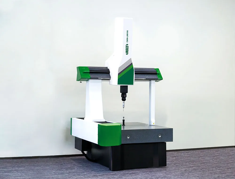
1. What Is a Coordinate Measuring Machine (CMM)?
A CMM measures the position of points in three-dimensional space using three perpendicular axes: X, Y, and Z. By collecting coordinate data from a workpiece, the software can calculate dimensions, evaluate geometric tolerances, and determine the relationships between different features.
Development of CMM Technology
CMM technology has developed through several stages:
• 1950s–1960s: The first CMM was developed in the UK in 1956. Early systems relied on manual data recording and calculations. Air-bearing guideways and measurement software were introduced during the 1960s.
• 1970s–1980s: Computer technology enabled CNC control and automated measurement functions. Touch-trigger probes also expanded measurement capabilities.
• 1990s–Present: CMM technology has continued to advance in measurement precision, automation, software, and non-contact measurement.
Today, CMMs are used to check dimensional tolerances, provide measurement data for product development, and support quality control in precision manufacturing.
2. What Can a CMM Measure?
A CMM can inspect basic dimensions, geometric tolerances, complex contours, and multiple parts of the same type.
Dimensional Measurement
CMMs measure features such as lengths, diameters, and hole sizes. Depending on the machine configuration and measurement conditions, they can provide micrometer-level measurement capability for checking parts against specified dimensions and tolerances.
Geometric Tolerance Inspection
CMMs can evaluate form and positional tolerances, including:
• Form: Flatness, roundness, and straightness.
• Orientation: Parallelism and perpendicularity.
• Location tolerance: Position, coaxiality and symmetry.
These measurements help determine whether individual features and their relationships meet drawing requirements.
Complex Contour Inspection
For workpieces with complex surfaces, a CMM collects measurement points along the required features and compares the measured geometry with the design model.
The resulting deviations can be used to evaluate manufacturing accuracy and identify areas that require adjustment.
Automated Batch Inspection
CMMs equipped with programmable control can follow predefined measurement paths to inspect multiple parts of the same type.
The same measurement program can be used across multiple workpieces, reducing manual operation and keeping inspection procedures consistent.
3. How Does a CMM Work?
A coordinate measuring machine (CMM) integrates the main frame unit, probing system, control and linear encoder systems, and software system to realize the acquisition and processing of three dimensional coordinate data.
3.1 Main Components of a CMM
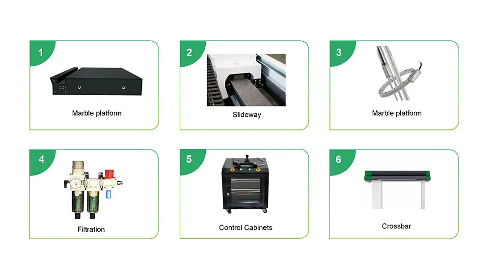
The main frame unit include the granite measuring table, guideways, air filtration components, control cabinet, crossbeam, and other structural components.
These components support workpiece positioning and controlled movement along the measuring axes.
Probing System
The probing system detects measurement points on the workpiece surface.
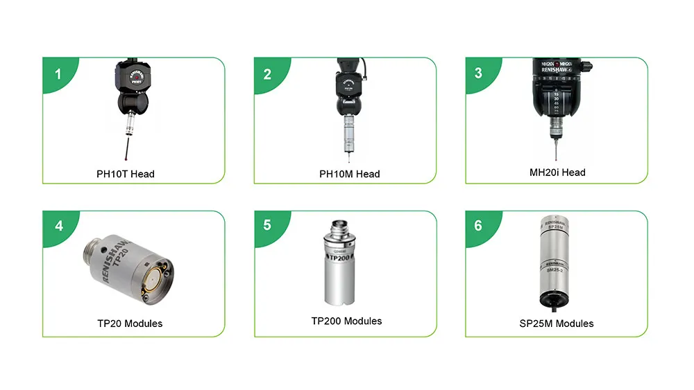
Common probe heads and modules shown here include the PH10T, PH10M, and MH20i probe heads, along with the TP20, TP200, and SP25M probe modules.
Different probe heads and modules are used according to measurement requirements and system configuration.
Control and linear encoder systems
The control system drives three axis motion and processes probe signals for signal interaction, while the linear encoder system feeds back the actual axis positions in real time; they work together to obtain the raw 3D coordinates of measuring points on the workpiece.
Software system
Its main functions include coordinate data processing, geometric feature evaluation, tolerance analysis, measurement result display, and report generation.
The measurement software communicates with the CMM control system to exchange measurement data and operating commands.
3.2 Understanding CMM Coordinate Systems
CMM measurement is based on the Cartesian coordinate system, which uses three mutually perpendicular axes: X, Y, and Z.
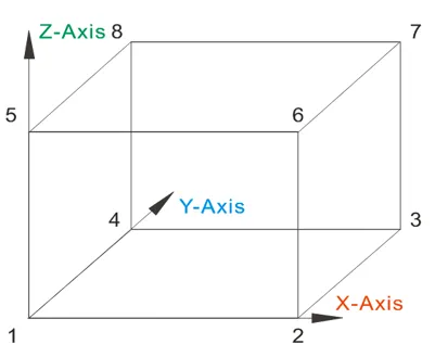
Each measured point is represented by a set of coordinates (X, Y, Z). These coordinates are used to calculate geometric features and evaluate their dimensions and positions.
Two coordinate systems are particularly important in CMM measurement.
Machine Coordinate System
The machine coordinate system is the fixed reference system defined by the CMM's mechanical structure.
Its origin is located at a defined position on the machine, and its axes correspond to the machine's movement directions.
This system provides the reference for recording measurement coordinates and establishing other coordinate systems.
Workpiece Coordinate System
The workpiece coordinate system is established according to the workpiece geometry and measurement requirements.
Its origin and axis directions can be defined using design datums, manufacturing references, or measurement features.
This allows measured dimensions and feature positions to be evaluated relative to the workpiece drawing rather than only to the machine's fixed coordinate system.
3.3 How CMM Measurement Data Is Collected
The basic measurement process follows these steps:
3.3.1 Place the workpiece on the measuring table and secure it.
3.3.2 Establish the required coordinate system.
3.3.3 Move the probe to the specified measurement positions.
3.3.4 Collect the X, Y, and Z coordinates of the measurement points.
3.3.5 Process the coordinate data to calculate geometric features and evaluate the measurement results.
The collected points are used to calculate geometric features such as lines, planes, circles, and cylinders.
The measured geometry can then be evaluated against the required dimensions and geometric tolerances.
3.4 CMM Movement and Control
CMM movement can be controlled manually or through a measurement program.
Manual Control
In manual operation, the operator uses a joystick to move the probe along the machine axes.
This allows the operator to position the probe according to the workpiece geometry and select measurement locations directly.
Manual control is useful when measurement positions need to be selected or adjusted by the operator.
Programmed Control
In programmed operation, measurement software defines the measurement points, probe paths, and movement speeds.
The CMM then follows the programmed instructions to perform the measurement sequence.
This method is particularly useful for repeated inspection of the same type of workpiece, where consistent measurement paths and procedures are required.
4. CMM Measurement Software: INSIZE DMIS
INSIZE DMIS is measurement software used for geometric measurement, feature construction, tolerance evaluation, and workpiece alignment.
4.1 Geometric Measurement
INSIZE DMIS supports measurement and evaluation of geometric features, including:
• Points, lines, and planes
• Circles, ellipses, and arcs
• Cylinders, cones, and spheres
• Keyways and other geometric features
These functions allow operators to measure individual features and evaluate their geometry.
4.2 Geometric Construction
The software can construct new geometric elements using measured features.
Available functions include intersection, projection, fitting, tangent construction, translation, offset, mirroring, and rotation.
These operations allow geometric relationships to be calculated from existing measurement data.
4.3 Geometric Tolerance Evaluation
INSIZE DMIS can evaluate dimensional and geometric relationships, including:
• Distance and angle
• Parallelism and perpendicularity
• Angularity and coaxiality
• Symmetry and position (2D and 3D)
• Circular runout and total runout
These evaluations help determine whether the measured features meet the specified geometric requirements.
4.4 Workpiece Alignment
Visual DMIS supports several methods for establishing a workpiece coordinate system, including:
• 3-2-1 Alignment: A coordinate system establishment method with graphical guidance.
• RPS Alignment: A reference-point-based positioning method commonly used in automotive fixture measurement.
• Best-Fit Alignment: Used for aligning measured geometry, particularly in surface measurement.
• Other Alignment Methods: Multi-point fitting, three-point offset, and two-point offset.
The appropriate alignment method depends on the workpiece geometry and inspection requirements.
5. Operating Precautions for INSIZE CMM Systems
The following precautions apply to the INSIZE CMM-LM, LE, PM, PE, GM, and GE Series.
5.1 Avoid vibration. Install the CMM away from vibration sources that may affect measurement accuracy.
5.2 Check the homing process. The machine performs automatic homing when powered on. Position workpieces carefully to avoid collisions during this movement.
5.3 Secure the workpiece. Clamp the workpiece firmly to prevent movement during inspection.
5.4 Clean the measurement surfaces. Remove oil, dirt, and burrs that could interfere with probe contact or measurement results.
5.5 Check the load capacity. For large or heavy workpieces, confirm that the weight does not exceed the machine's maximum load limit.
5.6 Handle workpieces carefully. Avoid impacts when placing, clamping, or removing parts from the measuring table.
5.7 Monitor probe clearance. When measuring complex workpieces from multiple angles, check the probe position and movement path to prevent collisions.
5.8 Clean and park the machine. Clean the measuring table and move the probe to the middle rear position before shutting down to reduce the risk of accidental contact.
Conclusion
CMM measurement relies on accurate coordinate data, proper workpiece alignment, controlled probe movement, and measurement software. Understanding these basic principles and following the correct operating procedures can help maintain consistent inspection results.